Power Factor Formula: How to Calculate It Correctly
If you’ve ever looked at an electricity bill and noticed a “power factor” charge, or you’re trying to size electrical equipment and keep running into the term, you’ve landed in exactly the right place. The power factor formula explains the relationship between the power your equipment actually uses and the total power your electrical system has to supply to deliver it — and understanding that relationship is the key to reading your equipment specs, your utility bill, and your system’s overall efficiency correctly.
This guide walks through the complete power factor formula for single-phase and three-phase systems, explains the power triangle that ties real, apparent, and reactive power together, covers typical power factor values for common equipment, and walks through several worked examples. By the end, you’ll know exactly how to calculate power factor and what the resulting number actually tells you.
Table of contents
- What Is the Power Factor Formula?
- How to Calculate Power Factor
- Power Factor Formula for Single-Phase Systems
- Power Factor Formula for Three-Phase Systems
- Power Triangle Explained
- Real Power vs Apparent Power vs Reactive Power
- Typical Power Factor Values
- Power Factor Correction Methods
- Power Factor Calculator
- Examples of Power Factor Calculation
- Why Power Factor Matters Beyond the Formula
- Conclusion
What Is the Power Factor Formula?
Power factor indicates how effectively an electrical system converts supplied power into useful output. A higher power factor reflects better energy utilization and improved system efficiency. Power factor ranges from 0 to 1, or 0% to 100% when shown as a percentage. A value of 1.0 indicates maximum efficiency, while lower values mean some of the supplied electrical power is not converted into useful work.
The core power factor formula is:
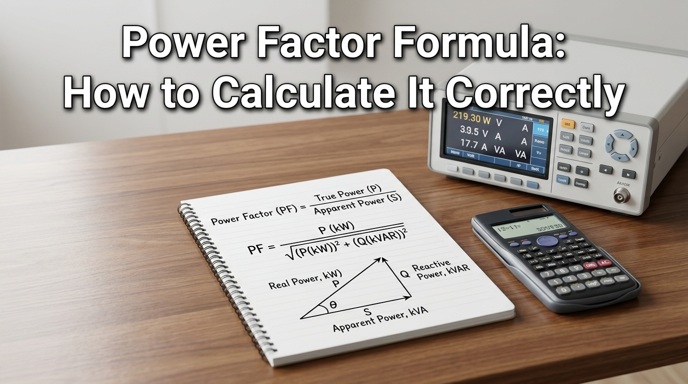
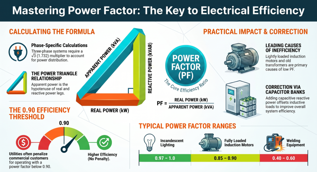
Power Factor = Real Power (kW) ÷ Apparent Power (kVA)
Real power is the power actually consumed to do useful work — running a motor, lighting a bulb, heating an element. Apparent power is the total power the electrical system has to supply, including the portion that’s used inefficiently due to reactive loads. The gap between these two numbers is what the power factor formula quantifies.
How to Calculate Power Factor
There are two common approaches to calculate power factor, depending on what data you have available: one based on power readings (kW and kVA), and one based on voltage, current, and phase angle (cos φ). Both give the same result when applied correctly to the same system.
To estimate appliance power consumption more accurately, use our Home Appliance Energy Calculator.
Power Factor Formula Using kW and kVA
This is the most commonly used version when you have access to a power meter or utility bill data:
Power Factor = Real Power (kW) ÷ Apparent Power (kVA)
For example, if a piece of equipment draws 8 kW of real power while the apparent power supplied is 10 kVA, the power factor is 8 ÷ 10 = 0.8, or 80%.
Power Factor Formula Using Voltage and Current
If kW and kVA values are unavailable, you can determine the power factor using the voltage, current, and phase angle. In this method, the power factor equals the cosine of angle between voltage and current waveforms.
Power Factor = cos φ
In this equation, φ (phi) refers to the phase angle that exists between the voltage and current waveforms in an AC circuit. A phase angle of 0° gives a power factor of 1.0 (perfectly in phase), while larger phase angles produce lower power factor values as voltage and current drift further out of sync.
Power Factor Formula for Single-Phase Systems
For single-phase circuits, the relationship between real power, apparent power, voltage, current, and power factor is:
Real Power (kW) = Voltage (V) × Current (A) × Power Factor ÷ 1000
Rearranged to solve for power factor directly:
Power Factor = Real Power (kW) × 1000 ÷ (Voltage × Current)
This version is particularly useful for residential and small commercial circuits, where you often know voltage and current from a meter reading but need to back-calculate power factor from those values combined with a measured real power figure.
Power Factor Formula for Three-Phase Systems
Three-phase systems include an additional √3 (approximately 1.732) factor to account for how power is distributed across the three conductors:
Real Power (kW) = √3 × Voltage (V) × Current (A) × Power Factor ÷ 1000
Rearranged for power factor:
Power Factor = Real Power (kW) × 1000 ÷ (√3 × Voltage × Current)
This formula is essential for industrial motors, commercial HVAC systems, and any three-phase electrical load, since applying the single-phase formula to a three-phase system will produce a noticeably incorrect result.
Once you understand real power consumption, use our Electricity Bill Calculator to estimate electricity costs.
Power Triangle Explained
The power triangle is a visual way to understand how real power, apparent power, and reactive power relate to each other. Picture a right triangle: real power (kW) forms the horizontal base, reactive power (kVAR) forms the vertical side, and apparent power (kVA) forms the hypotenuse connecting them.
This geometric relationship follows the Pythagorean theorem:
Apparent Power² = Real Power² + Reactive Power²
The angle between the real power base and the apparent power hypotenuse is the phase angle φ used in the cos φ version of the power factor formula. A smaller angle (closer to a flat triangle) means real power makes up most of apparent power, giving a power factor close to 1.0. A larger angle means reactive power is taking up a bigger share, pulling power factor down.
Real Power vs Apparent Power vs Reactive Power
Understanding the difference between these three measurements is essential to interpreting any power factor calculation correctly:
- Real Power (kW) — the actual power consumed to perform useful work, like turning a motor shaft or producing heat or light.
- Apparent Power (kVA) — the total power the electrical supply has to deliver, combining both real power and reactive power.
- Reactive Power (kVAR) — power that oscillates back and forth in the circuit due to inductive or capacitive elements (like motor windings or transformers) without performing any useful work itself.
A purely resistive load (like an incandescent bulb or electric heater) has essentially zero reactive power, so its real and apparent power are nearly equal, producing a power factor close to 1.0. Equipment with motors, transformers, or other inductive components always has some reactive power component, which is why their power factor is typically lower.
Leading vs Lagging Power Factor
Power factor falls into either the leading or lagging category based on the type of electrical load. Capacitive loads create a leading power factor, while inductive loads produce a lagging power factor.
- Lagging power factor occurs with inductive loads (motors, transformers), where current lags behind voltage. This is the most common situation in industrial and commercial settings.
- Leading power factor occurs with capacitive loads, where current leads voltage. This is less common as a natural condition but is intentionally introduced through power factor correction equipment to counteract lagging power factor elsewhere in a system.
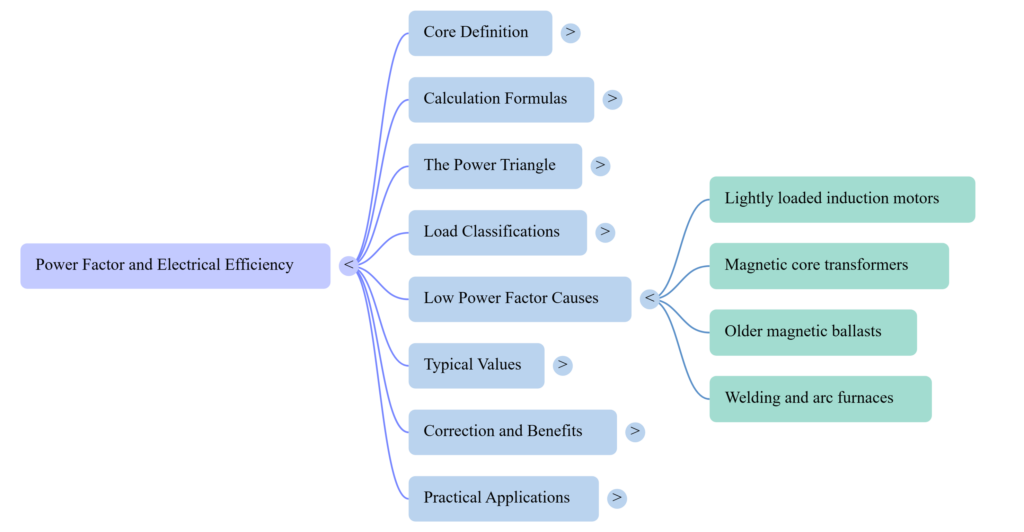
Causes of Low Power Factor
Several common factors contribute to a low power factor in electrical systems:
- Induction motors, especially when lightly loaded, which is one of the most frequent causes in industrial settings
- Transformers, which inherently introduce some reactive power due to their magnetic core design
- Fluorescent and discharge lighting with older-style magnetic ballasts
- Welding equipment and arc furnaces, which create highly variable, often inductive loads
- Old or poorly maintained equipment, which tends to operate less efficiently than well-maintained, modern alternatives
Power factor plays an important role in motor sizing and efficiency. Read our HP to kW Conversion guide for related calculations.
Typical Power Factor Values
Knowing what counts as a “good” or “typical” power factor helps put your own calculation results into context. Here’s a reference table of common typical power factor ranges for different equipment types:
| Equipment Type | Typical Power Factor |
| Incandescent lighting | 0.97 – 1.0 |
| Fluorescent lighting (modern ballast) | 0.90 – 0.95 |
| Induction motors (fully loaded) | 0.85 – 0.90 |
| Induction motors (lightly loaded) | 0.50 – 0.70 |
| Welding equipment | 0.40 – 0.60 |
| Electric heating elements | Close to 1.0 |
Most utility companies consider a power factor below 0.90 to be inefficient, and many apply financial penalties to commercial and industrial customers operating consistently below that threshold, which is part of why understanding and correcting power factor has direct financial value beyond just technical accuracy.
Power Factor Correction Methods
When a facility’s power factor is consistently low, several correction methods can bring it closer to 1.0:
- Capacitor banks — the most common correction method, adding capacitive reactive power to offset the inductive reactive power created by motors and transformers.
- Synchronous condensers — rotating machines that can supply leading reactive power, used more often in larger industrial or utility-scale applications.
- Active power factor correction (APFC) circuits — electronic systems built into modern equipment that automatically adjust to maintain a high power factor regardless of load conditions.
- Equipment upgrades — replacing older, inefficient motors or lighting ballasts with modern, higher-power-factor alternatives.
Benefits of Improving Power Factor
Correcting a low power factor delivers several practical benefits:
- Reduced electricity costs, since many utilities charge penalties for power factor below a certain threshold
- Lower current draw for the same real power output, reducing strain on wiring, transformers, and other infrastructure
- Improved voltage stability, particularly in facilities with multiple large inductive loads
- Extended equipment lifespan, since reduced electrical strain generally means less heat and wear on components
Power Factor Calculator
While the formulas above let you calculate power factor manually, a power factor calculator simplifies the process by letting you plug in known values — kW and kVA, or voltage, current, and phase angle — and get an instant result. This is particularly useful when you’re working with multiple pieces of equipment and want to quickly check several power factor values without redoing the math by hand each time. Power factor is also a direct input into other calculations, including amps-to-kW conversions and battery backup runtime estimates, which is why a solid understanding of this formula supports accuracy across several related electrical calculations.
Examples of Power Factor Calculation
Example 1: Single-phase residential circuit A circuit draws 230V and 10A, with a measured real power of 2 kW. Power Factor = (2 × 1000) ÷ (230 × 10) = 2000 ÷ 2300 ≈ 0.87
Example 2: Three-phase industrial motor A three-phase motor draws 415V and 50A, with a measured real power of 30 kW. Power Factor = (30 × 1000) ÷ (1.732 × 415 × 50) = 30000 ÷ 35,939 ≈ 0.835
Both examples land in the “typical” range for their equipment type — a residential circuit close to 0.87 and an industrial motor close to 0.84 — which matches what the reference table above would predict.
You can also read our Amps to kW Calculator guide to understand related electrical conversion formulas.
Common Power Factor Calculation Mistakes
A few mistakes show up repeatedly when people calculate power factor:
- Using the single-phase formula on a three-phase system (or vice versa), which produces a significantly incorrect result due to the missing or misapplied √3 factor.
- Mixing up kW and kVA, especially when reading equipment nameplates that list both values.
- Forgetting that power factor is unitless, mistakenly treating it as a percentage when the formula naturally produces a decimal between 0 and 1.
- Assuming a flat 0.8 power factor for all calculations without checking actual equipment specifications, which can lead to inaccurate sizing for backup power or electrical infrastructure.
Why Power Factor Matters Beyond the Formula
It’s easy to treat power factor as a purely academic number, but its real-world impact shows up in places most people interact with regularly, even if they don’t immediately connect it back to this formula.
On a commercial or industrial electricity bill, you may notice a separate line item for power factor penalty or reactive power demand charge. Utilities apply these charges because a low power factor forces them to generate, transmit, and distribute more current than would otherwise be necessary to deliver the same amount of usable energy. That extra current creates real costs across the entire grid — larger conductors, bigger transformers, and more line losses — and many utilities pass a portion of that cost back to customers whose facilities operate with a consistently low power factor.
For facility managers and electricians, this means power factor isn’t just a number to calculate once and forget. Seasonal changes in motor loading, the addition of new equipment, or even gradual motor wear can shift a facility’s overall power factor over time. Periodically recalculating power factor — especially after equipment changes — helps catch a developing problem before it shows up as an unexpected charge on a utility bill.
There’s also a practical sizing dimension that connects directly back to backup power planning. When you’re sizing a generator, UPS, or battery backup system for a facility with motors or other inductive loads, using the real power (kW) figure alone without accounting for power factor can lead to an undersized system that struggles under the actual apparent power (kVA) demand. This is exactly why power factor shows up as an input in amps-to-kW conversions and backup runtime calculations — it’s the bridge between the power your equipment supplies and the power your loads genuinely require.
Conclusion
The power factor formula might look intimidating at first glance, but it boils down to simple ratio: how much of the power your system supplies is actually doing useful work. Whether you’re using the kW-to-kVA version or the voltage-and-current cos φ version, the key is matching the correct formula — single-phase or three-phase — to your actual system, and understanding what a typical power factor looks like for the equipment you’re working with.
Explore our Smart Home guides for electrical calculations, energy efficiency, and appliance power usage.
The most valuable habit to take from this guide: never assume a flat power factor value without checking your actual equipment specifications, and always apply the correct phase-specific formula. That small extra step is what separates an accurate electrical calculation from one that quietly compounds errors into your backup power sizing, your equipment specs, or your utility bill interpretation.
Frequently Asked Questions
What is the formula for power factor?
Power Factor = Real Power (kW) ÷ Apparent Power (kVA), or equivalently, the cosine of the phase angle between voltage and current (cos φ).
What is a typical power factor for a motor?
A fully loaded induction motor typically has a power factor between 0.85 and 0.90, while a lightly loaded motor can drop to 0.50–0.70.
What is the difference between leading and lagging power factor?
Lagging power factor occurs with inductive loads like motors, where current lags voltage. Leading power factor occurs with capacitive loads, where current leads voltage.
Why is a low power factor a problem?
A low power factor means more current is required to deliver the same real power, increasing strain on electrical infrastructure and often triggering utility penalty charges for commercial and industrial customers.
How do you improve power factor?
The most common method is installing capacitor banks to offset inductive reactive power, though synchronous condensers and active power factor correction circuits are also used depending on the application.
Does power factor affect battery backup or amps-to-kW calculations?
Yes. Power factor is a direct input into both calculations — ignoring it, or using an incorrect typical power factor assumption, can meaningfully skew battery backup runtime estimates and amps-to-kW conversion results.