3 Phase Power Formula: Guide to Three-Phase Power Calculations
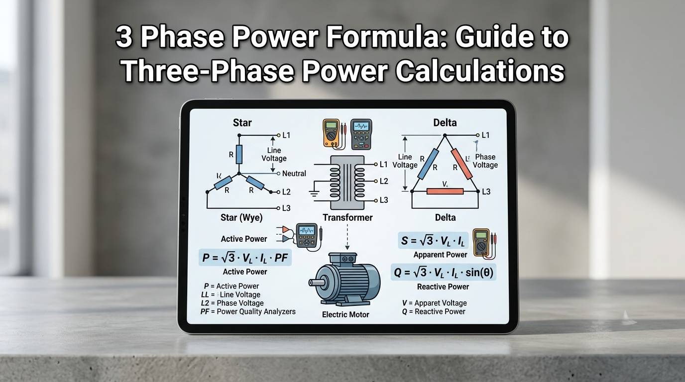
The 3 phase power formula is one of the most essential calculations in electrical engineering, industrial motor design and battery backup system planning. Three-phase power is the standard for commercial and industrial electrical distribution worldwide — virtually every large motor, transformer, generator, and power distribution system operates on three-phase power. Three phase power formula. Understanding the three phase power formula, how to apply it correctly, and when to use its different forms is a foundational skill for any electrical professional or technically minded facilities manager.
This guide covers everything: what the 3 phase power formula is and where the square root of 3 comes from, how to apply the three phase power formula in watts and kilowatts, how to work with power factor in three-phase calculations, the 3 phase current formula for sizing conductors and breakers, the 3 phase capacitor kvar calculation for power factor correction, and a complete formula reference table comparing single-phase and three-phase power equations side by side.
Table of contents
- What Is the 3 Phase Power Formula?
- Feature Breakdown: All Three Phase Power Formulas Explained
- Single-Phase vs. Three Phase Power Formula
- 3 Phase Capacitor kVAR Calculation for Power Factor Correction
- 3 Phase Power Formula for Motor Applications
- Pros and Cons of Three-Phase Power Systems
- Common Mistakes When Using Three-Phase Power Equations
- Which Three Phase Power Formula Should You Use?
- Conclusion
What Is the 3 Phase Power Formula?
The 3 phase power formula describes the relationship between voltage, current, and real power in a balanced three-phase AC circuit. Three-phase power systems operate with three conductors, each carrying an alternating current waveform that is offset by 120 degrees from the others, ensuring balanced and efficient power distribution. This phase relationship produces a constant, smooth power delivery that single-phase systems cannot match — which is why three-phase power is universally preferred for motors and large industrial loads.
The fundamental three phase power formula for real power (measured in watts or kilowatts) is:
P = √3 × VL × IL × PF
Where: P = Real power in watts (W) or kilowatts (kW) | √3 = 1.7321 (square root of 3) | VL = Line-to-line voltage in volts | IL = Line current in amperes | PF = Power factor (a dimensionless value between 0 and 1)
This is the complete 3 phase power formula used in virtually all practical electrical engineering and industrial applications. The square root of 3 appears because the three phases are electrically 120 degrees apart — the vector sum of three phasors separated by 120° produces a magnitude of √3 relative to each individual phase, which is what gives three-phase systems their power density advantage over single-phase.
Feature Breakdown: All Three Phase Power Formulas Explained
3 Phase Power Formula in Watts
When working in watts (rather than kilowatts), the three phase power formula is:
P (watts) = √3 × VL × IL × PF = 1.7321 × VL × IL × PF
Example: A balanced three-phase load drawing 25 amps on a 415-volt system with a power factor of 0.85 consumes:
P = 1.7321 × 415 × 25 × 0.85 = 1.7321 × 415 × 25 × 0.85 = 15,298 watts ≈ 15.3 kW
3 Phase Power Formula in kW
The three phase power formula in kilowatts divides the watt result by 1,000:
P (kW) = (√3 × VL × IL × PF) ÷ 1,000
For a 480-volt, three-phase system supplying a 30-amp load at 0.90 power factor:
P = (1.7321 × 480 × 30 × 0.90) ÷ 1,000 = (22,429) ÷ 1,000 = 22.43 kW
This is figure used for generator sizing, battery backup capacity planning, and transformer load calculations — always in kilowatts, not volt-amps.
For household electricity usage and estimated energy expenses, you can also use our Electricity Bill Calculator.
Three Phase Power Formula with Power Factor
The 3 phase power factor formula relates real power (kW), apparent power (kVA), and reactive power (kVAR) in three-phase system:
Power Factor (PF) = Real Power (kW) ÷ Apparent Power (kVA)
Or equivalently: PF = cos(θ) where θ is the phase angle between voltage and current
Apparent Power (S in kVA) = √3 × VL × IL ÷ 1,000
Reactive Power (Q in kVAR) = √3 × VL × IL × sin(θ) ÷ 1,000
The power factor formula for three-phase systems is particularly important for understanding the difference between the real power a system does useful work with (kW) and the total apparent power flowing through conductors (kVA).
To understand power factor calculations in more detail, see our Power Factor Formula guide.
A low power factor means conductors, transformers, and switchgear must carry more current than the useful load actually requires — which is why power factor correction matters in industrial settings.
3 Phase Current Formula
Rearranging 3 phase power formula to solve for current gives 3 phase current formula — used for sizing conductors and switchgear:
IL (amps) = P (watts) ÷ (√3 × VL × PF)
Or in kilowatts: IL (amps) = (P in kW × 1,000) ÷ (√3 × VL × PF)
Example: What current does a 50 kW, 460 V, three-phase load with power factor of 0.88 draw?
IL = (50,000) ÷ (1.7321 × 460 × 0.88) = 50,000 ÷ 701.8 = 71.2 amps
This current value (71.2 amps) is then used to select the appropriate conductor size (NEC Table 310.16 or 310.15) and overcurrent protection rating per NEC Article 430, ensuring the electrical infrastructure safely handles the three-phase load.
3 Phase Load Calculation Formula
For total 3 phase load calculation across multiple circuits or equipment in industrial facility, the total three-phase demand load is:
Total Load (kVA) = Σ (Individual Load kW ÷ Individual Power Factor)
Total Real Power (kW) = Σ Individual Load kW
The 3 phase load calculation formula aggregates all individual motor, lighting, heating, and equipment loads to determine the total kVA and kW demand on the supply transformer, main panel, and utility connection. This calculation is required for new facility design, transformer sizing, and demand charge management on utility tariffs.
For a better understanding of how multiple electrical appliances contribute to total system demand, read our Connected Load guide.
Single-Phase vs. Three Phase Power Formula
Understanding single-phase and three-phase power formulas helps compare loads accurately and supports smooth switching between different electrical system configurations .
| Parameter | Single-Phase Power Formula | Three Phase Power Formula |
| Apparent Power (S) | S = V × I | S = √3 × VL × IL |
| Real Power (P) | P = V × I × PF | P = √3 × VL × IL × PF |
| Power in kW | kW = (V × I × PF) ÷ 1000 | kW = (√3 × VL × IL × PF) ÷ 1000 |
| Reactive Power (Q) | Q = V × I × sin(θ) | Q = √3 × VL × IL × sin(θ) |
| Current Formula | I = P ÷ (V × PF) | IL = P ÷ (√3 × VL × PF) |
| Power Factor (PF) | PF = P ÷ (V × I) | PF = P ÷ (√3 × VL × IL) |
| Voltage Reference | Single line-to-neutral voltage | Line-to-line (line) voltage VL |
| √3 Factor | Not applicable | 1.7321 — accounts for 3-phase vector sum |
| Typical Application | Residential, lighting, small motors | Industrial motors, large HVAC, generators |
3 Phase Capacitor kVAR Calculation for Power Factor Correction
When power factor correction is required — either to improve energy efficiency, reduce utility demand charges, or comply with grid codes — capacitor banks are used to supply reactive power locally rather than drawing it from the utility. The 3 phase capacitor kvar calculation determines the correct capacitor bank size:
Required kVAR = P (kW) × (tan θ1 − tan θ2)
Where: θ1 = current power factor angle (cos⁻¹ of existing PF) | θ2 = target power factor angle (cos⁻¹ of desired PF)
Example: A 100 kW three-phase load currently operates at 0.75 power factor and must be corrected to 0.95 power factor:
θ1 = cos⁻¹(0.75) = 41.41° → tan(41.41°) = 0.8819
θ2 = cos⁻¹(0.95) = 18.19° → tan(18.19°) = 0.3287
Required kVAR = 100 × (0.8819 − 0.3287) = 100 × 0.5532 = 55.32 kVAR
A 55–60 kVAR capacitor bank is therefore required to correct this load from 0.75 to 0.95 power factor. Capacitor banks are specified in kVAR rather than kW because they supply reactive power, not real power — and the 3 phase capacitor kvar calculation always starts from the 3 phase power factor formula to establish the existing and target reactive power levels.
3 Phase Power Formula for Motor Applications
For three-phase motors specifically, the 3 phase power formula incorporates motor efficiency as well as power factor, because the motor’s electrical input power exceeds its mechanical shaft output by the amount lost to heat and friction.
If you need to convert motor horsepower into kilowatts before performing electrical calculations, use our HP to kW conversion guide.
Motor Electrical Input (kW) = (Motor HP × 0.7457) ÷ Motor Efficiency
Motor Input Current (amps) = (Motor HP × 746) ÷ (√3 × VL × Efficiency × PF)
For a 25 HP, 460 V, three-phase motor with 93% efficiency and 0.88 power factor:
Input Current = (25 × 746) ÷ (1.7321 × 460 × 0.93 × 0.88) = 18,650 ÷ 617.6 = 30.2 amps
This current value drives conductor sizing, breaker selection, and motor starter specification — all anchored to the 3 phase power formula applied with the motor’s real efficiency and power factor values rather than simplified approximations.
Pros and Cons of Three-Phase Power Systems
Why Three-Phase Power Dominates Industrial Applications
- Three-phase power delivers constant, ripple-free power — the three phases overlap so that the sum of all three voltages at any instant is always zero, producing steady torque in motors and stable lighting without flicker
- More power per conductor than single-phase — three-phase systems transmit approximately 1.73× more power through the same conductor cross-section, reducing copper costs and conductor weight
- Three-phase motors are inherently self-starting and produce smoother torque than single-phase motors, making them more efficient and longer-lasting under industrial duty cycles
- The 3 phase power formula scales linearly — doubling the load doubles the current without changing the voltage or frequency, making load planning straightforward
- Use the 3 phase power formula to size battery backup and generator systems that feed three-phase loads more precisely because it clearly defines the relationship between power factor and current.
Modern electrical planning also considers smart home technology, including connected switches, smart plugs, and automated lighting systems that help manage household electricity usage.
Complexity and Limitations to Be Aware Of
- The √3 factor in the three phase power formula is a source of error — forgetting it or applying it incorrectly produces calculations that are off by 73%, a potentially dangerous discrepancy in conductor and breaker sizing
- Three-phase power is uncommon in most residential electrical systems. If you need to operate three-phase equipment on a single-phase supply, you must use a suitable phase converter or transformer to ensure proper compatibility and safe operation.
- Unbalanced loading across three phases (different loads on L1, L2, L3) causes neutral current, increased losses, and reduced motor efficiency — the standard 3 phase power formula assumes balanced loads
- Power factor correction via 3 phase capacitor kvar calculation adds system complexity and requires periodic maintenance of the capacitor bank
For estimating the running cost of individual electrical appliances, use our Home Appliance Energy Cost Calculator to understand their electricity expenses.
Common Mistakes When Using Three-Phase Power Equations
Check the assumptions behind the 3 Phase Power Formula before relying on the result. These are frequent sources of incorrect calculations:
- Using phase voltage instead of line voltage: The line-value form expects line-to-line voltage. Mixing phase voltage with line current produces an incorrect result.
- Forgetting power factor: Multiplying √3, voltage, and current alone gives apparent power, not active power, unless PF is 1.
- Mixing watts and kilowatts: If voltage is in volts and current in amps, the result is watts. Divide by 1,000 to obtain kW.
- Assuming every load is balanced: The simplified equation may not represent an installation with substantially different phase currents.
- Confusing motor input and output power: A motor’s nameplate kW may refer to rated mechanical output. To calculate electrical input current, account for efficiency as well as PF.
- Treating cos φ as true PF in every system: Harmonic distortion can make true PF different from displacement power factor.
- Using nominal voltage without checking: Actual voltage can vary. Use appropriate measured or rated RMS values for the purpose of the calculation.
Which Three Phase Power Formula Should You Use?
For General Power Calculations (kW and kVA)
Use P (kW) = (√3 × VL × IL × PF) ÷ 1,000 for real power and S (kVA) = (√3 × VL × IL) ÷ 1,000 for apparent power. These are the two most frequently applied forms of the three phase power formula and cover the vast majority of industrial load calculations, generator sizing, transformer loading, and energy billing scenarios.
For Motor Circuit Sizing (Conductor and Breaker Selection)
Use the 3 phase current formula IL = P (watts) ÷ (√3 × VL × PF) to determine line current, then apply NEC motor circuit rules (125% of FLA for conductors per NEC 430.22, and up to 250% of FLA for inverse-time breakers per NEC 430.52). Always verify the result against the NEC Full Load Current tables (Table 430.250 for three-phase motors).
For Power Factor Correction Planning
Use the 3 phase capacitor kvar calculation: Required kVAR = P (kW) × (tan θ1 − tan θ2). This formula determines the exact reactive power compensation needed to bring any three-phase load from its existing power factor to the target level — essential for utility penalty avoidance and energy efficiency improvement in industrial facilities.
Conclusion
The 3 phase power formula is the foundation of electrical power calculations in industrial and commercial environments. From the basic real power equation P = √3 × VL × IL × PF through the three phase current formula, the 3 phase power factor formula, the 3 phase load calculation formula, and the 3 phase capacitor kvar calculation, every aspect of three-phase power system design and analysis flows from this single foundational relationship.
Applying the three phase power formula correctly requires understanding which voltage is the line voltage (VL), what the system’s power factor actually is rather than assuming it, and how motor efficiency modifies the electrical input current relative to the nameplate horsepower. With these variables properly identified and the √3 factor applied correctly, every downstream calculation — from battery backup sizing and generator selection to capacitor bank specification and conductor sizing — produces results that are safe, code-compliant, and accurate.
Whether you are planning a new industrial facility, sizing a battery backup system for a critical three-phase process load, or troubleshooting an overloaded transformer, the 3 phase power formula is the tool that makes every subsequent engineering decision defensible and precise.
Frequently Asked Questions
Why does the 3 phase power formula include √3?
The square root of 3 (√3 = 1.7321) appears in the three phase power formula because the three phase voltages and currents are 120 degrees apart. Measure the line voltage between any two line conductors and the phase voltage between any line conductor and the neutral, where the line voltage equals √3 times the phase voltage. When calculating total three-phase power using line quantities — which is the standard approach since line voltage is what meters and instruments measure — the √3 factor compensates for this geometric relationship between line and phase quantities.
What is the 3 phase current formula?
The 3 phase current formula rearranges the power formula to solve for line current: IL = P (watts) ÷ (√3 × VL × PF). In kilowatts: IL = (kW × 1,000) ÷ (√3 × VL × PF). Use this formula to determine the line current drawn by any three-phase load from its known power consumption, supply voltage, and power factor, and then select conductors and overcurrent protection devices accordingly.
What is the 3 phase power factor formula?
The power factor formula for three-phase systems is: PF = P (kW) ÷ S (kVA), where P is real power in kilowatts and S is apparent power in kilovolt-amperes. Apparent power is: S (kVA) = (√3 × VL × IL) ÷ 1,000. A power factor of 1.0 means all apparent power is doing useful work. A power factor below 0.90 typically indicates an opportunity for capacitor bank correction to reduce reactive power demand.
How do I perform a 3 phase load calculation?
A 3 phase load calculation aggregates all individual three-phase loads (motors, HVAC, lighting, heating) by summing their real power in kW and their reactive power in kVAR separately. Total real power: P_total = Σ P_individual (kW). Total reactive power: Q_total = Σ Q_individual (kVAR). complete apparent power: S_total = √(P_total² + Q_total²). Use this total kVA figure to size the supply transformer, verify main panel rating, and calculate overall facility power factor.
How do I calculate the capacitor kVAR needed for power factor correction on a three-phase system?
Use the 3 phase capacitor kvar calculation: Required kVAR = P (kW) × (tan θ1 − tan θ2), where θ1 is the angle corresponding to the existing power factor (cos⁻¹ of existing PF) and θ2 is the angle for the target power factor. For example, correcting a 75 kW load from 0.80 PF to 0.95 PF: tan(cos⁻¹ 0.80) = 0.7500; tan(cos⁻¹ 0.95) = 0.3287. Required kVAR = 75 × (0.750 − 0.3287) = 75 × 0.4213 = 31.6 kVAR. A 32–35 kVAR capacitor bank achieves the target correction.